1: Fundamental Concepts
1.3: Boundary Conditions: Constraints and Internal Conditions
If a displacement or relative displacement is freely allowed, the corresponding force will be zero.
1.3.1: Supports
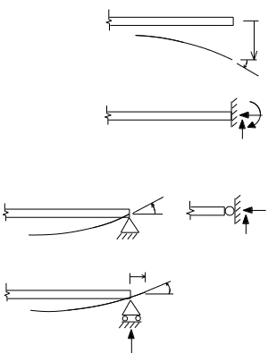 Fig. 1-6: Support Conditions
From Statics we are familiar with beam support conditions. The free end of a beam shown in Fig. 1-6 rotates and displaces without restraint and carries no moment. The rigid wall cannot rotate or displace and the end of the beam at the wall is capable of carrying moment and shear, and (especially important for an inclined built-in member) an axial force component could also be applied by the wall.
The pinned support is illustrated in two ways in Fig. 1-6. This support condition prevents any translational displacement at the point of connection, but rotation is permitted. The moment must be zero at a pin. The version of the pin support to the right in Fig. 1-6, which we will use occasionally in sketches of frames and arches, has been included as a sort of limiting case of an internal articulation point, which will be described presently. Normally the triangular shaped pinned support on the left will be depicted in this text.
The roller support allows both a rotation, and also a displacement along the direction of the plane on which the roller bearings sit. No displacement, either up or down (in the configuration shown) is permitted. The roller can create neither a moment nor a reaction force along the direction of rolling.
1.3.2: Conditions
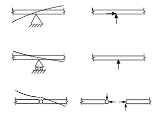 Fig. 1-7: Internal Conditions (Support and Release)
In the analysis of general beam and frame systems we must be able to deal with internal support and release conditions as well as end support conditions. In the next chapter and throughout the book we will encounter many beam and frame systems with combinations and variations of these conditions. Three internal conditions are illustrated in Fig. 1-7, the first two being support conditions and the third a release condition.
The pinned support in Fig. 1-7 provides 2 reactions as shown. There is no applied moment reaction, however, there is an internal bending moment and slope continuity of the elastic curve of the structure must be satisfied across the support.
The roller support shown in Fig.1-7 provides one reaction force, and as with the pinned support the continuity of slope of the elastic curve is maintained across the support.
At the internal hinge there is no bending moment. There are no external reactions, but both internal axial force and shear are possible in general. The internal condition can be stated briefly as follows. The beam remains connected at this point, but the connected elements are free to articulate about it.
1.3.3: Contrived Supports and Conditions
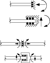 Fig. 1-8: Contrived end and internal conditions
The conditions pictured in Fig. 1-8 are called contrived. As unusual and impractical as these might appear, we may find these useful in “statically indeterminate analysis” coming up later, where we will have to create our own “released structures” which may well involve the cases shown in the figure.
The external end reactions, and the internal member forces that accompany each of these conditions are shown.
It is useful to classify the top two of these as supports, and the bottom two as internal release conditions.