
T20: W Brace
Example T20: W Brace with Reduced cross-section
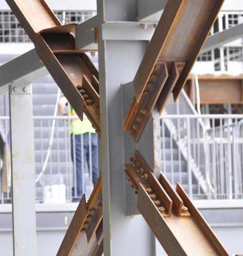
This example shows the computation of the factored tension resistance of a W shape used as a tension member in a lateral brace in a building such as that shown in the following photo. There are 4 braces shown. Note that the upper left brace has the flange tips removed from the W-shape (to ensure ductility under seismic forces). We will compute the strength of a brace similar to that shown in the photo.
from Designer import DesignNotes, SST, Part, show
%figure "DSC6443-small.jpg"
import pint                  # setup to use the module for computing with units
ureg = pint.UnitRegistry()
mm = ureg['mm']
inch = ureg['inch']
kN = ureg['kN']
MPa = ureg['MPa']
ureg.default_format = '~P'
notes = DesignNotes('Tr',units=kN)      # initial the note/record keeping object
RECORD = notes.record     # useful abbreviations
CHECK = notes.check
USEVARS = notes.usevars
%figure "brace1.svg"
Note that 40mm is cut from each flange tip of the W250x67.
%figure "angle.svg"
class Bolts(Part):
    "Bolts"
    grade = 'ASTM A325'
    size = '3/4"'
    d = (3/4*inch).to(mm)
    Fu = 825*MPa
    Ab = 3.14159*d**2/4.
    n = 4                    # number of bolts per end
    s = 75.*mm                  # bolt spacing
    threads_intercepted = True

Bolts.show()
class Angles(Part):
    "Angles"
    grade = 'CSA G40.21 350W'
    Fy = 350*MPa
    Fu = 450*MPa
    d,b,t,Ag,size = SST.section('L102x76x13','D,B,T,A,Dsg')
    d = d*mm
    b = b*mm
    t = t*mm
    Ag = Ag*mm*mm
    ha = (22 + 2)*mm  # hole allowance  - punched holes
    g1 = 65*mm        # gauge, longer leg
    g2 = 45*mm        # gauge, shorter leg
    s = 80*mm         # dist between innermost holes on each end

Angles.show()
CHECK(False,'Bolting and fitting details have not been checked.')
phiu = 0.75

with USEVARS(('d,b,t,ha,g1,g2,Fu,s',Angles),
             ('n',Bolts),
             locals='wg,wn1,g,wn2,wn,An,Ane', globals='phiu',
             record='Tr',label='Net section fracture, 4 angles',
             ):
    # gross width = "flattened" width of angle:
    wg = d + b - t

    # failure path 1-1: 1 hole
    wn1 = wg - 1*ha

    # failure path 2-2: 2 holes
    g = g1 + g2 - t
    wn2 = wg - 2*ha + s**2/(4*g)

    wn = min(wn1,wn2)

    An = wn*t
    Ane = 0.8*An if n >= 4 else 0.6*An   # S16-14: 12.3.3.2 (b) (i) - connected 1 leg n lines of bolts

    Tr = 4. * phiu*Ane*Fu    # S16-14: 13.2 a) iii)
phi = 0.9
with USEVARS(('Ag,Fy',Angles),
            label='Gross section yield, 4 angles'):
    Tr = 4. * phi*Ag*Fy    # S16-14: 13.2 a) i)
with USEVARS(('t,d,b,g1,g2,ha,Fy,Fu',Angles),
             ('n,s',Bolts),
             locals='Agv,An,Ut',
             label='Block shear, 4 angles'):
    Agv = (40*mm + (n-1)*s)*t
    An = (min(d-g1,b-g2) - ha/2.)*t
    Ut = 0.3     # SUPER conservative
    Tr = 4. * phiu*(Ut*An*Fu + 0.6*Agv*(Fy+Fu)/2.)
%figure "w.svg"
class WShape(Part):
    "WShape"
    grade = 'ASTM A992'
    Fy = 345*MPa
    Fu = 450*MPa
    Ag,b,d,t,w,size = SST.section('W250x67',properties='A,B,D,T,W,Dsg')
    Ag = Ag*mm*mm
    b = b*mm
    d = d*mm
    t = t*mm
    w = w*mm
    wp = 190*mm          # width of web reinforcing PL
    tp = 8*mm            # thickness of web reinforcing PL
    wc = 40*mm           # width cut from flange tips
# Path 1-1: net = gross  +  plates  -  holes
with USEVARS(('ha',Angles),
             ('Ag,tp,wp,w,Fu',WShape),
             locals='An,Ane',
             label='Net section fracture, W shape'):
    An = Ag  +  2*tp*wp   -  2*ha*(w+tp+tp)
    Ane = 0.85*An    # S16-14: 12.3.3.2 (c) (i)
    phiu = 0.75
    Tr = phiu*Ane*Fu
with USEVARS(('Ag,wc,t,Fy',WShape),
             locals='Agr',
             label='Gross section yield, W shape'):
    Agr = Ag - 4*wc*t   # reduced area due to flange cuts
    phi = 0.9
    Tr = phi*Fy*Agr     # S16-14: 13.2 a) i)
with USEVARS(('ha,g2',Angles),
             ('w,tp,Fy,Fu',WShape),
             ('n,s',Bolts),
             locals='Agv,An,Ut',
             label='Block shear, W shape'):
    T = w + tp + tp          # thickness of web + reinforcing plates
    Agv = 2*(40*mm + (n-1)*s)*T
    An = (g2 + g2 + 25*mm - ha)*T   # estimate 25mm spacing between angles (gusset thickness)
    Ut = 1.0
    phiu = 0.75
    Tr = phiu*(Ut*An*Fu + 0.6*Agv*(Fy+Fu)/2.)       # S16-14: 13.11
with USEVARS(('w,tp,Fy,Fu',WShape),
             ('n,s',Bolts),
             locals='An,Ahv,Ut',  label='Tearout, W shape'):
    Agv = 4*(40*mm + (n-1)*s)*T
    An = 0*mm*mm
    Ut = 1.0
    phiu = 0.75
    Tr = phiu*(Ut*An*Fu + 0.6*Agv*(Fy+Fu)/2.)       # S16-14: 13.11
with USEVARS(('n,s,Ab,Fu,threads_intercepted',Bolts),
             locals='m,L',    label='Bolt Shear'):
    phib = 0.8
    m = 2
    Tr = 0.6*phib*n*m*Ab*Fu * 2   # S16 13.12.1.2.b)
    L = (n-1)*s   # length of connection
    if L >= 760*mm:
        Tr = Tr * (0.5/0.6)
    if threads_intercepted:
        Tr = Tr * 0.7
with USEVARS(('t,Fu',Angles),
             ('n,d',Bolts),
             record='Br', label='Bolt Bearing (on 4 angles)'):
    phibr = 0.8
    Br = 3*phibr*n*t*d*Fu * 4
with USEVARS(('w,tp,Fu',WShape),
             ('n,d',Bolts),
             locals='t',     record='Br', label='Bolt Bearing (on web of W)'):
    t = w+tp+tp
    Br = 3*phibr*(n*2)*t*d*Fu
notes.summary()
Notes
- Note that gross section yield of the W should govern, but it does not, by a large margin.
- Obviously, more bolts are required, or detail them so that threads are not intercepted (risky for installation considerations).
- Another thing to try would be slightly larger angles. Perhaps L127x76x13 (which would not require any additional space between flanges).
- Or could shave a few more millimeters from flange tips.
- Of course, all this has to be compared with factored applied loads.